Wednesday, December 18, 2013

A customised 737 Panel ...

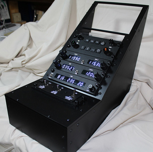
We don't offer a lot of 737 products as there are already plenty of quality manufacturers in this market and there's not really much else that we could normally offer over and above what's already available. Recently, however, we've been working with a customer who has specific space limitations and therefore custom measurements are required to properly house the panels in their rightful places.

After much testing and verification in our workshop to prove the possibilities, the panel will be used by our customer with his PMDG 737-800 NGX software via one of our 64 Input Boards for the switches, and a Conditional 64 Output Board to drive the LEDs in the annunciators.


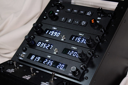
And so this is the Boeing 737 N1 SET / SPD REF / AUTO BRAKE Panel that we dispatched to him a couple of weeks back, complete with our newly developed backlighting process. We haven't implemented this backlighting technique across our entire product range at the moment, as due to time restraints - and getting work out to customers - its become more of a panel by panel expansion (I guess that would be the best way to describe it!) ...


Alongside the panel itself, we also made the functioning combination switches  which include a rotary switch, and an encoder (with pushbutton also if required). As you can tell from the positioning of the text, we've actually used some 30 degree rotaries as the 45 degree switches we had access to weren't able to be readily altered for the purposes required.


As a one-off type of project, a small section of vero board has been used to mount the small MFD switches, which isn't perhaps very pretty but gets the job done all the same! The photo below shows the panel about 80% wired.


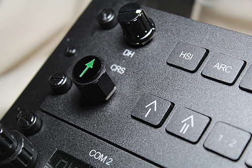
A notable couple of omissions on this panel are obviously the two annunciators that accompany it, because we had already built these previously for our customer, so we simply built the rest of the panel around these measurements and the overall dimension constraints for the panel that were originally provided to us. The dual concentric knobs are designed and manufactured by us as well.


We've also improved our engraving technique lately as well, which is hopefully demonstrated by the picture above. It takes a little longer to accomplish, but the results are certainly worth it ...

Friday, November 29, 2013

Some newly completed radios

As always there's too much work to be done to keep up with all that we'd like to post about, although we did manage to take a quick video of some newly completed radios the other day ...


[Although the blog feels like it's been in something of a holding pattern for a while now, we have ambitious plans of uploading much more of what we've been doing for the past few months, as we've been kept on our toes with a variety of interesting projects ... ]

Friday, October 18, 2013

Bell 206 Avionics Stack

A quick post on a frantic Friday afternoon linking to a video of a Bell 206 Avionics Stack that we made for a customer recently. A more in-depth post about this project will be written up shortly, but in the meantime, a couple of photos and the video ... 


Friday, July 12, 2013

Customised Vertical Speed Unit

Always good for keeping us on our toes, we were recently asked by a customer in South Africa to build a customised Vertical Speed Unit based around a truncated version of the Operational Altitude Alert System that we already make, and which was ordered at the same time.

Some new code had to be written especially for the Vertical Speed processor chip of course, which had to allow for both positive and negative values etc, and after much testing and fine-tuning this is all now working as expected. We should have taken a video(!) but instead a few photographs will have to suffice as evidence.


As something as an aside here, our Altitude Alert software has also recently been updated so as to allow for altitude settings below 1000ft; functionality that's often a requirement for helicopter simulators. 

Friday, June 28, 2013

The Main BK-117 Caution Panel

As the final post dealing with the various parts we've been designing for a BK-117 helicopter simulator, this component is by far the largest single piece although was relatively painless to manufacture (panel-wise) due its being based around our standard 30x10 annunciators. Aside from making the appropriate surround to fit our client's dimensions, it was really just a matter of customising the legends as necessary.

There are terminals for a 'Lamp Test' button to be connected, and in 
the photo above you can see that it has been connected and pressed! 

[Here's a shot of the original layout our panel was based on. 
The legends differ in places due to each Caution Panel 
reflecting a slightly different configuration.]

Cold and dead.

The LED boards that are shown fitted to the rear of the panel are actually truncated versions of those that are typically used in our King Air MIP Annunciator Panels. The matrix for those units are 6 x 6 whereas here we needed to use a 5 x 5 matrix. Designing the PCB layout (so that the PCBs can be readily used for either variation) was an interesting process and the most time-consuming for this particular piece of hardware.

The cables and PCBs will eventually be interfaced via our Conditional 64 Outputs Board, which uses RJ45 connections. Note, however, that headers are also fitted so that it can be interfaced in another way if desired.

Thursday, June 27, 2013

BK-117 AP Select Panel

Another part for the BK-117 project, this time the AutoPilot Select Panel.

The same buttons were incorporated here as on the AP Actuator Panel 
discussed in an earlier post, although the LEDs were yellow in this instance. 
This part was again designed to be fitted as a single piece after all of the 
necessary wiring had been done as all of the backing pieces are attached 
to the front panel. It is, of course, able to be fully dismantled 
- although hopefully there'll never be any need to!

This particular unit will be interfaced via FSUIPC and one of our 
PCBs but as it's all just LEDs and switches, it can be readily 
interfaced however one wishes.


A lower shot to highlight the various depths of the button-heads 
and finger guards, and the relative sturdiness of the entire assembly.
[The original image that we were asked to work off.]

And here's our very earliest prototype. Most of our prototypes 
are made in clear acrylic as doing so allows us to better view 
and calculate all of the rebates and pocketing from all angles 
without having to constantly flip the pieces back and forth 
in order to understand what's going on. 

Small BK-117 AP Panel

Continuing with the BK-117 ...

The sizings for this panel meant that we were actually able to use 
our standard replica Korry buttons and surrounds without any 
modifications, which might seem like a small, not particularly noteworthy 
coincidence, although things like that can greatly reduce the design time.

After a multitude of tests using a variety of different light-blocking 
techniques, our attempts to stop excessive light bleed into the surrounding 
material (and therefore the neighbouring legend!) was finally accomplished 
via a combination of cleared material (creating an air gap) and paint.

Testing the brightness of the LED glow beneath the full glare of our 
workbench's fluorescent lights. Most simulators are in partial darkness 
of course, but it's always nice to try and have the lighting noticeable 
in daylight, which might be the normal circumstances of an aircraft's flight.
[The original image our panel was designed around]

BK-117 Actuator Panel

As one component of a much larger job, we recently designed the 
panel shown below for a local company's BK-117 simulator. 


[This is an image of the original panel which we were asked to replicate.]

It was designed as a complete unit that could be neatly fitted into 
place once the appropriate wires had been fitted. Each button 
has been fitted with two 3mm LEDs and a switch, which will eventually 
be wired up and interfaced via one of our PCBs and FSUIPC.


The LED recesses behind each buttonhead can be clearly seen in this 
earlier prototype, of which several were made before we had a workable 
solution that accounted for all of the various depths involved regarding 
switches, guards, buttonheads, clearances etc ... !

Wednesday, March 20, 2013

RAI Intercoms

As a result of some recent inquiries we've written up some new details regarding the capabilities of our flight simulation intercom units, including a couple of new diagrams that might be of some use also.


Our intercoms are not normally supplied with microphone and headphone sockets, but we are able to supply aviation microphone sockets, and stereo headphone sockets, and indeed we have recently supplied some special Helicopter Headset sockets because they have the mic and phones on the same plug.

Heli Sockets

All connections to our intercom boards is via screw terminals.

The microphone input circuitry is suitable for most microphones, and can even be readily configured for very low impedance microphones as used in some military and vintage headsets. (or Oxygen masks)

There are on-board adjustments for the gain of the microphone, and the level of the "side-tone" (so you can hear your own voice).  There are also volume adjustments for the audio signals coming from the PC, and because we can drive stereo headphones, you can hear cockpit / engine sounds coming from the correct location.  There is a master volume control fitted on a short cable to enable you to fit it into your panel as required.

There are several modes of operation for the intercoms, with two pairs of terminals which control the outgoing audio. These are logic levels only, so you can fit remote buttons and switches, because there is no audio signals on these wires.

1. One allows you to connect a 'Push to Talk' button so that the other pilot can hear you only while you hold the button down, or you can just put a small wire link between the two terminals and you can be heard all the time. (Open Microphone) 

2. The other pair of terminals allows you to connect an 'Enable' switch to enable or disable the audio going to the Flight Simulator PC. If you want audio to go the Flight Simulator PC all the time, just put a small wire link between the two terminals.

3. Another option is to connect the system so that you have an Open Microphone (as in 1 above) and then use a ‘Push to Talk’ button on the Enable terminals. The means that the pilots can hear each other all the time, but the push to talk button controls what goes out to the Flight Simulator PC. (e.g.  as a radio call etc.)


4. If you use a double pole push-button  (one pole connected to the ‘Push to Talk’ terminals, and the other pole connected to the ‘Enable’ terminals) you can effectively have a push to talk button so that the other pilot can only hear you whilst the button is depressed, and also your voice only goes out to the Flight Simulator PC while the button is held down.

Friday, February 22, 2013

Conditional 64 Outputs Board

Over the past few weeks we've made some fairly significant changes to our 64 Outputs Board software which greatly improve its versatility. Below is a basic overview of what these alterations are, although more detailed posts regarding some of the aspects detailed here will likely follow in the next few weeks.

Also, the details on our website haven't been able to keep up with us, and these will be updated in the coming days. The PCBs themselves are the same (as indeed will be the price!), but the programming of the processor chips and the software interface behind them have been altered.

Anyway, on to the improvements ... 

Upgrade 1: Configurable Warning System now available

We have now added a Warning function to four outputs on our 64 Outputs Board. This allows users the ability to add a large number of conditions that can be used to trigger various warning lights. (Master Warning, Master Caution etc.)

We have allowed these special Warning outputs to use outputs 7 and 8 on banks 7 and 8.

The system works by having up to two specific conditions that must be true (ie. Battery Master, and Avionics Master etc.) (or they can be left blank) followed by any one of up to another 25 conditions being true.

One (or any) of these four warnings can also have a physical switch connected to the Ruscool 64 Outputs Board, which will act as a Reset button for the particular Warning light when it is activated. This means that if the Warning light is triggered, it can be turned off (reset) by pressing the button, and the Warning light will turn on again if another condition re-triggers the warning. If the warning condition resets itself, or an action by the pilot corrects the fault, the warning lamp will go out without the need to press the reset button.

The example below will light the Warning output if the Battery Switch and Avionics Switch are 'On' and any of the other conditions are true.


Upgrade 2: Configurable Switches added

Another new feature is that users now have the ability to connect to three inputs for use as custom switches or pushbuttons as well.

As shown in the example below, the first switch is set as 'momentary', which means that it will operate as a pushbutton toggle action.  


You can use these switches to control any FSUIPC offset or FS Control (event). They are labelled as 5, 6 and 7 because the first 4 switches are dedicated to the Warning resets and switch 8 is dedicated as a lamp test switch (more of which is explained below).

Upgrade 3: New Lamp Test options

There are now two options for how the lamp test can be operated.

Method 1: The lamp test can be triggered by the user through the assigning of an offset which will then be used to trigger the lamp test. When this offset is changed, the outputs that have been 'flagged' will be lit. 


This can either be a valid FSUIPC offset, or any unused (reserved) offset that you are using
either from a Ruscool 64 Input board, another input controller or from within Flight Simulator. The offset type must be a single byte that sends either "1" or "0".

Method 2: A physical switch can be connected to the Ruscool 64 Outputs board and the lamp test can be controlled that way. Switch 8 on the 64 Outputs board is dedicated to this function.

You can also specify whether the lamp test is only triggered if the battery bus has voltage or whether it's always triggered regardless of the battery status.

Eg. Offset Trigger


Eg. Switch Trigger

Monday, February 18, 2013

A re-design of our ATR Autopilot Panel

A few years have elapsed since we designed the first version of our ATR Autopilot Panel and so, using some newer techniques that we've developed in the interim - along with some slightly altered dimensions - this panel has recently undergone some design alterations.

Below are some photographs of the prototype ...

For photographic purposes, the buttons here are only temporarily 
attached to the rear of the panel with masking tape.

It's difficult to show here, but the engraving of the panel isn't on the front surface, where it would be exposed to a lot of wear due to the pilot's operation of the trim wheel.


By means of comparison, below are a couple of shots showing the earlier version 
(circa 2005)


Thursday, February 14, 2013

Cessna Citation Range: extended (and modified)

Over the past couple of months or so, as a result of some new information being provided to us by one of our customers who's currently building a Cessna Citation Mustang sim, we've been able to incorporate some measurements that now resemble those of the actual aircraft much more closely. 

As regards to the products that were previously up on our website, these changes affect the dimensions of the Left Switch Panel, the Right Switch Panel, the Lighting Panel (all of which are considerably smaller), and the Landing Gear Panel also, although to a much lesser extent.   

As well as these alterations, we've also added a few more bits and pieces to our Cessna Citation range of products, including the Oxygen Control Valve Panel, the Test Panel, and IAS Placard (all on the MIP), and the Oxygen Supply Panel too, which is part of the main sub-panels.

Oxygen Control Valve Panel: The knob that is fitted here should actually be black, although as we were supplying this particular panel without any of its associated hardware, this was actually just one of the spares that we already had in stock (and used for photographic purposes ...) 

IAS Placard: not much to explain here ...

Oxygen Supply Panel: The asymmetrical appearance of this particular panel is due to its location on the extreme right-hand side of the sub-panel set. Attached is a push/pull switch with a flat aluminium knob fitted to it.

Test Switch Panel: complete with two-step knob

Combined Sub-Panel Layout

Lighting Panel: This panel has now been updated with the correct cut-out into which the throttle quadrant would normally sit. We're hoping to organise a Cessna Citation throttle kit set (similar to the King Air kit that we currently sell), although this is likely to be some months away yet.

As well as updating the dimensions of the Left Switch Panel, we've also altered the appearance of the starter buttonheads too. The previous photos and drawings that we'd worked off had always shown simple black buttonheads, although these designs are a bit fancier.

Here they are temporarily in position, though not held in place with the usual mounting bracket and switches that we can supply if required by our customers.

The Landing Gear Lever (above), although not overly affected by the measurement changes, has undergone something of an upgrade with regards to the indicators that are now housed within it. These small annunciators are actually part of a separate item that gets affixed to the rear of the panel itself (incorporating a new design that will be discussed in a subsequent post shortly). You'll notice too, that in this particular shot, there's a simple hole through which the gear lever protudes. This was due to our customer's request and the units that we typically sell have a 13mm vertical slot into which our own gear lever assembly can be fitted.