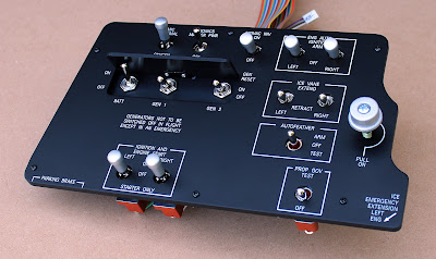
Another B200 panel that has a different configuration from the standard B200 panels that we sell. This panel was customised for the B200 simulator that we recently built for a local customer, and included all of the wiring!
Friday, July 05, 2024
Replica Pro Line Fusion Console Controls
This complete module package includes dual controllers—one specifically for the MKP and another for the operation of the CCPs and SKPs.
B200 ELT Panel and Housing
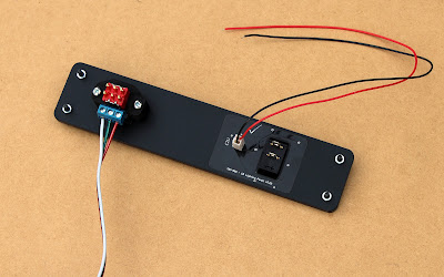
Also for the previously mentioned B200 simulator, situated just behind the Fuel Module on the Captain's side, this panel contains a replica Emergency Locator Transmitter (ELT), as well as a dummy gauge for the outside temperature.
Replica GCU477
B200 Captain Left Panel
Last year we overhauled an entire B200 simulator with a newly-designed set of panels that mimic those found in the real aircraft, as our customer was replicating it for training purposes.
Here are some photos of the Captain Left Panel ...
Friday, October 21, 2022
TBM-900 Main Instrument Panel (DXF)
We're not in a position to be able to offer a full TBM-900 main instrument panel, although because we needed to draw up an initial design around which we could organise the panels that we do make, we thought that these drawings might provide a useful starting point for someone beginning to build a simulator, instead of the files simply hiding away in our file system ...
The DXF (along with a PDF file) can be downloaded directly from our website on the following page (you'll need to scroll through to find it): https://www.ruscool.co.nz/Panel-Cutouts-Dimensions/
Below is a quick image of the model from which the DXF is derived.
- Master Caution Button
- Master Warning Button
- De-Icing Panel
- Park Brake Panel
- Gear Panel
- ECS Panel
- CB Lighting Panel
- Static Source Selector Panel
- Crew Music Panel
- 15" MFD Unit
The DXF for the main instrument panel only shows the hole cutouts and mounting screw positions of the aforementioned panels (not their outer dimensions), although the drawings for these can be downloaded from the same page as the MIP design.
There are, of course, still several other items needed for a full TBM cockpit that you'll want to include, but which we don't sell ourselves - such as the GMC710, the GCU475, and the G1000 units. These parts will need to be added to your design separately, and suppliers who manufacture these items will likely be able to provide you with the necessary dimensions so that you can incorporate them.
Wednesday, September 28, 2022
Additional TBM-900 panels
Over the past few months we've designed several new TBM-900 panels to go with our existing range ...
Circuit Breaker Lighting Panel
This panel includes one of our replica Korry buttons, which in the above photos is shown without any lighting. In the photo below, the lower half of the Korry has been illuminated. Our replica Korry pushbuttons have been designed to fit into the same footprint as a real Korry 389 button, as shown in a previous post about our B350 Reversionary Panels, so they can be swapped out if required.
This panel, with the exception of the coloured vinyl decals and the dummy circuit breakers themselves, is fully backlit by a circuit board that's recessed into the main panel itself.
Whilst we only fit dummy circuit breakers to it, the panel has been designed so that these can be readily replaced by real circuit breakers if required. There are several PDFs on our website that contain not only the panel dimensions and required panel cutout, but also the spacing and layout of the circuit breakers, so that the fit of any real breakers can be checked/verified prior to purchasing.
And this is what the fully-assembled panel looks like from the rear ...
Monday, March 07, 2022
Fusion Pedestal for King Air B350
As we've been documenting in the past few posts, here's the finished and fully-assembled pedestal panel that we recently completed for a King Air B350 simulator.
And a quick shot of the pedestal prior to painting and engraving etc.
Sunday, February 20, 2022
Fusion-style MKP for the B350 Pedestal
The multifunction keyboard panel (MKP) is the third and final component that we manufactured for the B350 Pedestal Plate we completed recently. As mentioned in earlier posts, this module was based on the Pro Line Fusion range of hardware.
The Pan/Zoom knob is a four-direction hat switch, which also has encoder and pushbutton functions as well.
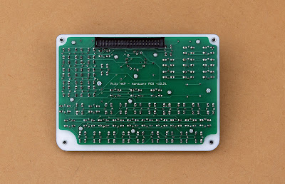
A box header allows the unit to be connected to a controller via a 40-way ribbon cable.
There's no actual backlighting on the panel itself, but all of the buttonheads are illuminated.
Friday, February 11, 2022
Fusion-style CCP Panels for the B350
There's a pair of these to be found on the pedestal plate: one either side of the MKP (which we've also just completed, and which will be posted here shortly) ...

The TAB knob operates a four-directional hat switch, that's also a single encoder, and which has a pushbutton action too. Unfortunately we weren't able to replicate the exact functionality of the real unit, as this actually calls for a dual encoder/hat switch combination - and with eight directions as well!
We tried our best to find a solution - one involving all sorts of internal gears that required the mounting of an additional hidden encoder - but in the end we were unfortunately forced to realise our limitations. Our solution actually got pretty close to working, but was nowhere near reliable enough to run with. Instead, the two separate TAB knobs are effectively one, as they're both mounted to the hat switch, albiet individually.
In the above image, you can see some remnants of our attempt at producing a makeshift dual-encoder hat switch, as this originally required a second hardware PCB (not shown) that would be positioned on a set of stand-offs which would then be mounted on the rear of the circuit board that you see here. So there's a lot of superfluous circuitry on display - not all of which can be explained by what's seen from the front!
The panel's backlighting, and that of the buttonheads, runs on 12V.


