Saturday, July 26, 2014

Our RNS430 and RNS530 Units

... or rather, our take on the Garmin GNS430 and GNS530 respectively.

We've had quite a few requests for these units over the years and after making our version of the Aspen EFD1000 we thought that we'd try to apply the same sort of process to these Garmin units.

There are actually three versions of the RNS430 and RNS530, as we've found that each simulator is being made or (more likely) has already been constructed in a certain way and any additional navigation units need to be able to fit around and/or into these constraints.

The types are basically (a) the Bezel Only, which can be used in front of an already installed MIP LCD screen, (b) the Bezel Only plus a fitted LCD screen - but with no interface board, or (c) the Bezel with a fitted LCD screen and its integrated interface board.

The versions that we're showing below are the Bezel Only units, as they just happen to be the ones that we got the first orders for; although, paradoxically, they're also the most difficult to make.

The dimensions of our units as compared with the official Garmin panels are below:

Ruscool RNS530: 162mm(w) x 120.4mm(h) / 6.38" x 4.74"
Garmin GNS530: 159mm(w) x 117mm(h) / 6.25" x 4.60"

Ruscool RNS430: 162mm(w) x 83mm(h) / 6.38" x 3.27"
Garmin GNS430: 159mm(w) x 67mm(h) / 6.25" x 2.65"


And now, on to the photos ...  the RNS430 first


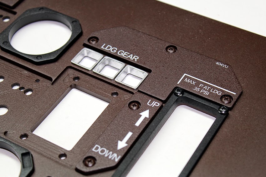
 The three screws that you can see here are the means by which 
the unit is mounted onto the main instrument panel.

And below, again as the Bezel Only version, is the RNS530


Avionics Display for a Bell 412 Simulator

This was part of an interesting project that we were contacted about a while ago and which involves using second-hand iPad display screens behind some bezels that we designed and are in the process of supplying (two have been delivered and two are on the way).


Thankfully the company we're working with were happy to send one of the actual iPad screens all the way down here to New Zealand for us to take accurate measurements of and with which  to work our original prototyping around. The end result was actually a press-fit of the screen into the rear of the bezel, although of course there are also screws holding it in place, with four convenient little corner tabs already being a part of the screens' outer construction.


As you can see, some of the tolerances between the PCBs and the outer edges of the bezels are fairly tight due to our measurements being as faithful to the original avionics unit as we could possibly get them, although because these units are being fitted into instrument panels that are being laser-cut after the arrival of the bezels themselves, it means that accurate measurements can be taken from the actual pieces themselves, in situ as it were.


The company that's going to be using these units are actually doing all of the interfacing themselves, so the circuit boards merely provide a means of communicating with the switches.

And finally ... 


 The ghost in the machine!

Some work on the ATR Simulator ...

It's been a while since any work has really been done on my own ATR simulator, although over the Christmas holiday break this year (wow, that was a while back now!) I managed to get a few things done. Most of the work was behind-the-scenes sort of stuff, with some programming work being carried out that allows yet more overhead buttons and annunciators to be properly interfaced, although a visible portion of the progress (and the one most obvious to visitors) is the newly made Central MIP, which overlays the PC monitor.

Below are a few quick photos, the first image being the Central MIP prior to painting and the fitting of the gauge bezels and other panels et cetera ...


And below is the original photograph of an actual ATR72 cockpit that I was lucky enough to go and visit a few years back, and which the design of the above panel(s) was based on. There are discrepancies with various measurements here and there due to space constraints and the like, although hopefully the overall essence of the panel has been maintained. 


There's not really too much to show with regards to the additional interfacing that was accomplished on the overhead as the majority of it related to implementing some of the new abilities on our Input and Output cards, although I did have the overhead section down from above the simulator for the first time in a long while and so took a coupe of shots of it.


And I'm guessing that'll be about it unless we can find time for some Christmas holidays again this year ... !

Fibreglass King Air Yokeheads

Below are a few of shots of the King Air B200 yokeheads that we recently supplied to a local customer. The moulds themselves were taken from a real yokehead, and as is painfully obvious in these photos, they are clearly shown here in their raw form. We sell them in this rough state because we've found that a lot of builders would prefer to spend the time wiring the yokeheads themselves in order to save the money that's involved with us offering a complete, fully-wired set of parts (funds that can no doubt be spent elsewhere!) ...


An example of the detail achieved during production.

As we've already completed a set of these during the construction of the C90 simulator, below are also some photographs and explanations of our techniques and reasons, which might help anybody who's chosen to use a similar method. This is by no means the only way of dong things, of course!

First, the pieces themselves. As you can see, there are eight separate pieces that make up a pair: 2 x front sections, 2 x back sections, 2 x upper yokehead mounting, 2 x lower yokehead mounting. All of these individual parts are hollow, meaning that the larger main sections especially are still a little fragile at this stage. This can be remedied by filling certain sections of the yokeheads with a filling material later.

These yokehead mountings may also be filled, a rocker switch for the trim fitted, and two switches (for the AP Disconnect and the Push to Talk ) can then also be installed and wired.

The above photograph - from our previous King Air C90 build - shows where we've applied the filling compound. This is done in order to strengthen the entire head and also enables various holes to be readily drilled and tapped as necessary. 

Having arrived in the same condition as the first few photos, the entire unit has now been sanded to within an inch of its life, wired, and fitted together. You might also notice the aluminium plate that's now fitted inside the base of the unit; this provides greater stability and allows for the yokehead to be fitted very securely to the stem of the yoke.


The view from the back: prior to the wires being connected from the top section to the base, after which the entire unit is connected.

And the (almost) finished product - prior to fitting the timer in the pilot's side, the aluminium plate in the first officer's, and fitting the final mountings etc. ...