Pages

Showing posts with label BK-117. Show all posts

Friday, June 28, 2013

The Main BK-117 Caution Panel

As the final post dealing with the various parts we've been designing for a BK-117 helicopter simulator, this component is by far the largest single piece although was relatively painless to manufacture (panel-wise) due its being based around our standard 30x10 annunciators. Aside from making the appropriate surround to fit our client's dimensions, it was really just a matter of customising the legends as necessary.

There are terminals for a 'Lamp Test' button to be connected, and in 
the photo above you can see that it has been connected and pressed! 

[Here's a shot of the original layout our panel was based on. 
The legends differ in places due to each Caution Panel 
reflecting a slightly different configuration.]

Cold and dead.

The LED boards that are shown fitted to the rear of the panel are actually truncated versions of those that are typically used in our King Air MIP Annunciator Panels. The matrix for those units are 6 x 6 whereas here we needed to use a 5 x 5 matrix. Designing the PCB layout (so that the PCBs can be readily used for either variation) was an interesting process and the most time-consuming for this particular piece of hardware.

The cables and PCBs will eventually be interfaced via our Conditional 64 Outputs Board, which uses RJ45 connections. Note, however, that headers are also fitted so that it can be interfaced in another way if desired.

Thursday, June 27, 2013

BK-117 AP Select Panel

Another part for the BK-117 project, this time the AutoPilot Select Panel.

The same buttons were incorporated here as on the AP Actuator Panel 
discussed in an earlier post, although the LEDs were yellow in this instance. 
This part was again designed to be fitted as a single piece after all of the 
necessary wiring had been done as all of the backing pieces are attached 
to the front panel. It is, of course, able to be fully dismantled 
- although hopefully there'll never be any need to!

This particular unit will be interfaced via FSUIPC and one of our 
PCBs but as it's all just LEDs and switches, it can be readily 
interfaced however one wishes.


A lower shot to highlight the various depths of the button-heads 
and finger guards, and the relative sturdiness of the entire assembly.
[The original image that we were asked to work off.]

And here's our very earliest prototype. Most of our prototypes 
are made in clear acrylic as doing so allows us to better view 
and calculate all of the rebates and pocketing from all angles 
without having to constantly flip the pieces back and forth 
in order to understand what's going on. 

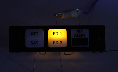
Small BK-117 AP Panel

Continuing with the BK-117 ...

The sizings for this panel meant that we were actually able to use 
our standard replica Korry buttons and surrounds without any 
modifications, which might seem like a small, not particularly noteworthy 
coincidence, although things like that can greatly reduce the design time.

After a multitude of tests using a variety of different light-blocking 
techniques, our attempts to stop excessive light bleed into the surrounding 
material (and therefore the neighbouring legend!) was finally accomplished 
via a combination of cleared material (creating an air gap) and paint.

Testing the brightness of the LED glow beneath the full glare of our 
workbench's fluorescent lights. Most simulators are in partial darkness 
of course, but it's always nice to try and have the lighting noticeable 
in daylight, which might be the normal circumstances of an aircraft's flight.
[The original image our panel was designed around]

BK-117 Actuator Panel

As one component of a much larger job, we recently designed the 
panel shown below for a local company's BK-117 simulator. 


[This is an image of the original panel which we were asked to replicate.]

It was designed as a complete unit that could be neatly fitted into 
place once the appropriate wires had been fitted. Each button 
has been fitted with two 3mm LEDs and a switch, which will eventually 
be wired up and interfaced via one of our PCBs and FSUIPC.


The LED recesses behind each buttonhead can be clearly seen in this 
earlier prototype, of which several were made before we had a workable 
solution that accounted for all of the various depths involved regarding 
switches, guards, buttonheads, clearances etc ... !

Friday, October 05, 2012

BK-117 Dummy Gauge

As one of a few customised projects that we've been working on lately, this is a (very) small dummy gauge that's destined for a local BK-117 helicopter simulator. The outside measurements of the gauge (not including the mounting bracket) are 36mm; a physical size that's not really conducive to its being made functional. 


Below is a larger-than-life photograph showing it in more three-dimensional detail ...