Pages

Saturday, July 26, 2014

Some work on the ATR Simulator ...

It's been a while since any work has really been done on my own ATR simulator, although over the Christmas holiday break this year (wow, that was a while back now!) I managed to get a few things done. Most of the work was behind-the-scenes sort of stuff, with some programming work being carried out that allows yet more overhead buttons and annunciators to be properly interfaced, although a visible portion of the progress (and the one most obvious to visitors) is the newly made Central MIP, which overlays the PC monitor.

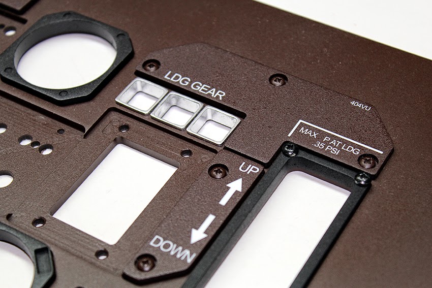
Below are a few quick photos, the first image being the Central MIP prior to painting and the fitting of the gauge bezels and other panels et cetera ...


And below is the original photograph of an actual ATR72 cockpit that I was lucky enough to go and visit a few years back, and which the design of the above panel(s) was based on. There are discrepancies with various measurements here and there due to space constraints and the like, although hopefully the overall essence of the panel has been maintained. 


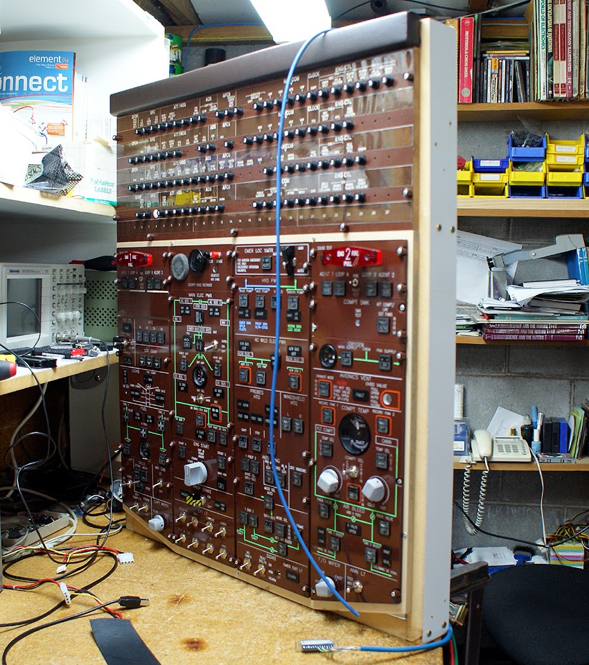
There's not really too much to show with regards to the additional interfacing that was accomplished on the overhead as the majority of it related to implementing some of the new abilities on our Input and Output cards, although I did have the overhead section down from above the simulator for the first time in a long while and so took a coupe of shots of it.


And I'm guessing that'll be about it unless we can find time for some Christmas holidays again this year ... !

Fibreglass King Air Yokeheads

Below are a few of shots of the King Air B200 yokeheads that we recently supplied to a local customer. The moulds themselves were taken from a real yokehead, and as is painfully obvious in these photos, they are clearly shown here in their raw form. We sell them in this rough state because we've found that a lot of builders would prefer to spend the time wiring the yokeheads themselves in order to save the money that's involved with us offering a complete, fully-wired set of parts (funds that can no doubt be spent elsewhere!) ...


An example of the detail achieved during production.

As we've already completed a set of these during the construction of the C90 simulator, below are also some photographs and explanations of our techniques and reasons, which might help anybody who's chosen to use a similar method. This is by no means the only way of dong things, of course!

First, the pieces themselves. As you can see, there are eight separate pieces that make up a pair: 2 x front sections, 2 x back sections, 2 x upper yokehead mounting, 2 x lower yokehead mounting. All of these individual parts are hollow, meaning that the larger main sections especially are still a little fragile at this stage. This can be remedied by filling certain sections of the yokeheads with a filling material later.

These yokehead mountings may also be filled, a rocker switch for the trim fitted, and two switches (for the AP Disconnect and the Push to Talk ) can then also be installed and wired.

The above photograph - from our previous King Air C90 build - shows where we've applied the filling compound. This is done in order to strengthen the entire head and also enables various holes to be readily drilled and tapped as necessary. 

Having arrived in the same condition as the first few photos, the entire unit has now been sanded to within an inch of its life, wired, and fitted together. You might also notice the aluminium plate that's now fitted inside the base of the unit; this provides greater stability and allows for the yokehead to be fitted very securely to the stem of the yoke.


The view from the back: prior to the wires being connected from the top section to the base, after which the entire unit is connected.

And the (almost) finished product - prior to fitting the timer in the pilot's side, the aluminium plate in the first officer's, and fitting the final mountings etc. ...

Friday, May 09, 2014

A customised panel

Below are a few quick shots that show the left-hand sub-panel from a much larger custom job that we're currently working on for one of our customers. 

As we're doing the majority of the interfacing here in our workshop prior to shipping the whole constructed unit to him, we've integrated a custom backlighting panel which also doubles as a backing plate for all of the hardware. Doing this means that the whole panel now becomes an entirely separate module that can be easily removed as one piece, allowing us to do the wiring and testing away from the main instrument panel itself if need be.


Wednesday, April 02, 2014

First installation of the RMC710 Autopilot

Late last week we completed the first installation of our new RMC710 Autopilot System into a local customer's King Air C90 simulator that we've been helping with. The post previous to this one explained most of the panel's details but we've now uploaded a short video of it operating to our YouTube channel as well.


Throughout this build we've customised a few components here and there and thought that this might be a good opportunity to share some of them, seeing as the astute amongst you will no doubt have noticed some differences to previous builds we've been involved with.

One of the most immediately noticeable differences is the colour scheme, which is a medium grey colour. This is probably illustrated by the following panels, as photographed whilst still in our workshop.


Actually (and if you've watched the above video, rather obviously), the above MIPs were made for a previous customer and incorporated the addition of two small Marker Beacon Indicators, each positioned at the top left of their respective panels. A more detailed photograph of one of these is below, although because of the amount of light in our workshop - and no available tripod upon which to mount the camera - it's a little difficult to see the illumination that we'd temporarily hooked up behind the blue legend. In person as it were, however, we were very pleased with the result.


Okay then, back to our local customer's simulator ... 

Below, you can see the two display units that had previously been purchased from another supplier and which were to be incorporated into the new build. We designed the main instrument panel around these and then the real work began: re-working the interfacing of the MFD and the PFD - although that's another post entirely if we ever find the hours needed to detail it. You can probably tell from the subsequent photos how involved the process was ... !


Oh, and skipping to the once again operational MFD and PFD ...


The LCD1000 all fired up

Alright then, so we've finally managed to put some time aside in order to re-establish access to the appropriate drivers, video outputs, and software needed to hook up the LCD1000.

Below are some initial photos (excuse the dust!), and a video with some commentary will be made shortly. In fact, if you haven't already seen it, we put up a video a while back which demonstrated how it operated using the 'bezel only' version of this panel, which can be found here.


There are a couple of minor issues for us to tidy up here and there, as this unit was essentially our first prototype, but to give you an idea of costings, these units will be sold for US$570-00. If you're interested (or have any questions), please feel free to contact us directly, as our products are typically available for purchase well before we get the time to actually advertise them properly on our website.

Friday, March 21, 2014

Evolution of the Ruscool LCD1000 Unit

For the past few months we've been selling a bezel complete with buttons and encoders (see the first two photographs), which is based around the Aspen EFD1000. It was designed to fit in front of an LCD monitor upon which the appropriate graphics were shown, with our PCB interfaced to its software, thus making the unit operational.


Below is a short video on our Youtube account demonstrating its functionality using the Flight1 Aspen software. It it also able to use the Aspen EFD1000 software from Friendly Panels.


This product has recently undergone something of a facelift, however, and has since been significantly upgraded and taken to a much more realistic level, having now evolved into the Ruscool LCD1000; a stand-alone unit complete with its own LCD screen.


As seen from the shot above, with the ability to now fit the unit actually into a panel as would properly occur in an aircraft, the thickness of the panel is much reduced. Similarly, with the LCD display unit now embedded deep into the panel itself, there is a substantially more realistic and aesthetically pleasing result with regards to the distance from the panel's surface to the graphics.


Jumping out at everybody - I'm sure - is the fact that the display isn't actually displaying anything! Rest assured that this is simply a logistical issue at present, due to some temporary relocations of computers and monitors about our workshop, and shall be remedied as soon as possible so that we can update matters with a proper video and some more details. It still uses the Flight 1 Aspen software, or the Friendly Panels Aspen software.

In the meantime, and going right back to the earliest origins of this product, below are some shots from a few months back that some might consider interesting: our first operational prototype of the 'bezel only' version ...


Friday, February 14, 2014

Operational Autopilot System - RMC710

This is an early preview of one of the many new items that we've been developing in the background over the past few months: an operational Autopilot System (the Ruscool RMC710), which is based around the Garmin Mode Controller (GMC 710) ...

The text on the faceplate is backlit, and all the buttons are able to be illuminated when their particular function is selected. The rotary encoders have pushbuttons like the real unit, and the roller wheel for the Vertical Speed adjustment has notches to allow for ease of turning,

The unit has been designed to fit into a separate backing plate which is then attached to the main instrument panel. This is currently being painted however, and we haven't got any decent photos of this yet (it was made yesterday), but we shall remedy this once the entire unit has been installed and is up and running in our customer's simulator. He lives locally too - which is mighty convenient!


Despite this system being designed around our own I/O boards, as with the majority of our products, wherever possible we also make each individual connection available directly from the PCB (see above photograph) so that our customers can use whichever interface system they wish. One reason to employ our own I/O boards is of course that all of the software and its capabilities are known to us, although an additional benefit is that we also have the ability to customise some of the logic as and when necessary.

And this is how it looked prior to the fitting of the buttonheads and knobs, the application of paint, and the completed engraving. You can just make out the backlit buttons through the open buttonholes.

Oops, what do you know ... the painting of the backing plate was finished and dried before we'd completed this post, so below is a quick photo of the assembled faceplate fitted into this particular version of backing plate.

As with all initial concept items, there are several slight alterations with regards to a few details here and there - such as replacing the mounting screws some more realistic countersunk types, and the concealment of the encoder nuts - which will be implemented on subsequent versions.

Wednesday, December 18, 2013

A customised 737 Panel ...

We don't offer a lot of 737 products as there are already plenty of quality manufacturers in this market and there's not really much else that we could normally offer over and above what's already available. Recently, however, we've been working with a customer who has specific space limitations and therefore custom measurements are required to properly house the panels in their rightful places.

After much testing and verification in our workshop to prove the possibilities, the panel will be used by our customer with his PMDG 737-800 NGX software via one of our 64 Input Boards for the switches, and a Conditional 64 Output Board to drive the LEDs in the annunciators.


And so this is the Boeing 737 N1 SET / SPD REF / AUTO BRAKE Panel that we dispatched to him a couple of weeks back, complete with our newly developed backlighting process. We haven't implemented this backlighting technique across our entire product range at the moment, as due to time restraints - and getting work out to customers - its become more of a panel by panel expansion (I guess that would be the best way to describe it!) ...


Alongside the panel itself, we also made the functioning combination switches  which include a rotary switch, and an encoder (with pushbutton also if required). As you can tell from the positioning of the text, we've actually used some 30 degree rotaries as the 45 degree switches we had access to weren't able to be readily altered for the purposes required.


As a one-off type of project, a small section of vero board has been used to mount the small MFD switches, which isn't perhaps very pretty but gets the job done all the same! The photo below shows the panel about 80% wired.


A notable couple of omissions on this panel are obviously the two annunciators that accompany it, because we had already built these previously for our customer, so we simply built the rest of the panel around these measurements and the overall dimension constraints for the panel that were originally provided to us. The dual concentric knobs are designed and manufactured by us as well.


We've also improved our engraving technique lately as well, which is hopefully demonstrated by the picture above. It takes a little longer to accomplish, but the results are certainly worth it ...

Friday, November 29, 2013

Some newly completed radios

As always there's too much work to be done to keep up with all that we'd like to post about, although we did manage to take a quick video of some newly completed radios the other day ...


[Although the blog feels like it's been in something of a holding pattern for a while now, we have ambitious plans of uploading much more of what we've been doing for the past few months, as we've been kept on our toes with a variety of interesting projects ... ]

Friday, October 18, 2013

Bell 206 Avionics Stack

A quick post on a frantic Friday afternoon linking to a video of a Bell 206 Avionics Stack that we made for a customer recently. A more in-depth post about this project will be written up shortly, but in the meantime, a couple of photos and the video ... 


Friday, July 12, 2013

Customised Vertical Speed Unit

Always good for keeping us on our toes, we were recently asked by a customer in South Africa to build a customised Vertical Speed Unit based around a truncated version of the Operational Altitude Alert System that we already make, and which was ordered at the same time.

Some new code had to be written especially for the Vertical Speed processor chip of course, which had to allow for both positive and negative values etc, and after much testing and fine-tuning this is all now working as expected. We should have taken a video(!) but instead a few photographs will have to suffice as evidence.


As something as an aside here, our Altitude Alert software has also recently been updated so as to allow for altitude settings below 1000ft; functionality that's often a requirement for helicopter simulators.