Pages

Friday, February 17, 2017

ATR Engine Start Panel

As mentioned in this blog previously, the simulator that we have in our workshop is based on an ATR-72 and has become something of a test-bed for various components over the years without having had the time to properly complete it. The overhead panels shown there were the first iteration of ATR componentry that we used to sell.

Recently though, as the result of a specific customer request for some ATR overhead panels, we have embarked upon something of a re-design process utilising the same techniques that we've begun implementing across our entire range of panels. This includes fully backlighting them.

The first panel that we've just completed is the Engine Start Panel, as shown below:


The above photo (when compared with the photo below) gives some indication as to the amount of separation there is between neighbouring legends which are housed on the same annunciator; there is no light bleed whatsoever between the two halves.


Similarly below, in the korry switch that displays 'FAULT' there is no bleeding of the amber light into the well of the legend which reads 'ON' (and vice versa, had I thought to take a photo of it!)


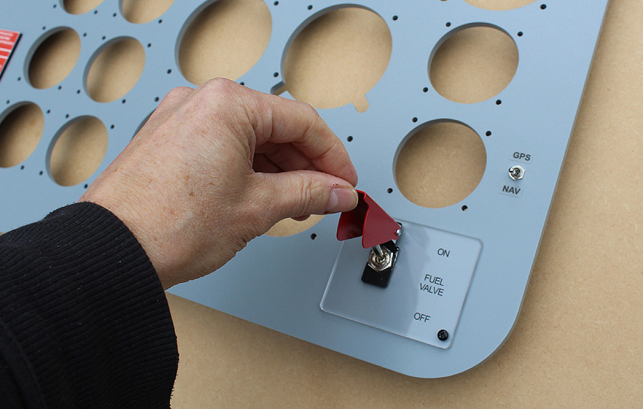
Another challenge was the Prop Brake switch latch, which had to be loose enough to operate but tight enough not to fall open on its own accord (it's upside-down above one's head, of course). This problem was overcome by fitting a small customised spring onto one side of it.


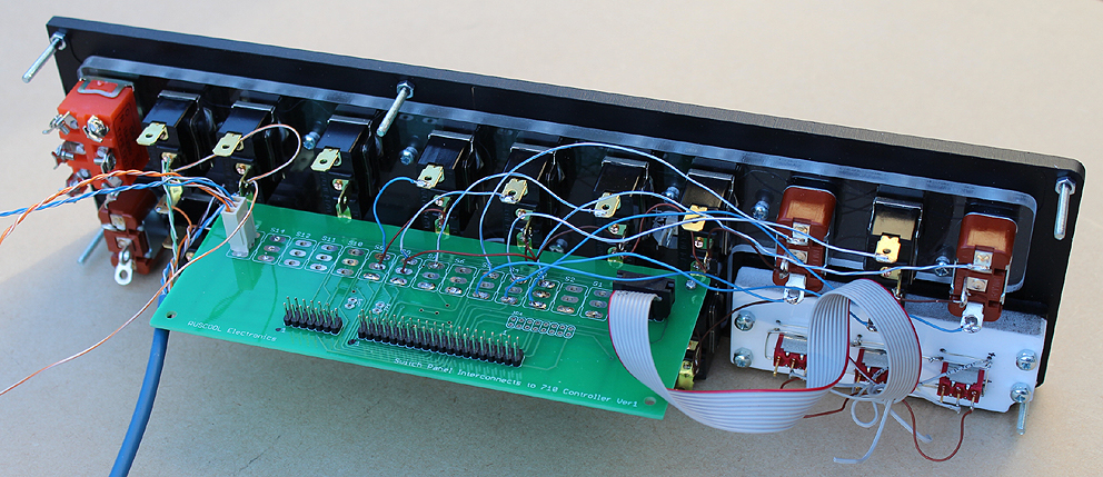
Below is a photograph of what the panel looks like from the rear. You can see that it's supplied as one fully-populated unit, with all of the components pre-fitted to various mounting plates. For connecting up the korry switches, we've fitted 3-way connectors, which hopefully make things a bit more convenient and will lead to our customer spending more time flying and less time soldering!


Below is a very quick video (without any commentary) which demonstrates (hopefully) some sense of how solid the korry switches sound, and how 'positive' their action is ...

Friday, December 23, 2016

Simkits version of our Bell 206 MIP

We were recently contacted by a customer who wanted to use some gauges from the Simkits range in one of our Bell 206 main instrument panels.

Here is the result:


The height of the panel is slightly less than one of our standard versions because there is no concern here about the MIP having to cover the entire front of an LCD monitor.


Because of the way this will eventually be mounted, we were also able to mount the fuel valve switch (along with its panel) and the GPS/NAV toggle switch directly onto the front surface of the instrument panel. Normally these are spaced off a little bit so as to allow the componentry to sit flush against a monitor and not poke holes in it! No such concerns here though, all of which helps to keep the price down of course.


This panel, whilst not actively advertised on our website, can of course be purchased. The price (without the annunciator panel that's shown fitted in these photographs) is US$257-00.

Custom Airbus Parts

We don't offer too many Airbus parts because there are already some fantastic products available elsewhere, although we do like helping to provide parts and panels that can't be easily found or which need to be built around specific dimensions and/or requirements.

The panels shown here were built for a simulator that incorporated various aspects of both an A350 and A380. We supplied a basic configuration file based around our own 64INS and 64OUT I/O Boards, which were interfaced to the Jeehall Airbus software.

Landing Gear Panel


Note: we actually had to re-make this front panel because it 
didn't survive the 19,000km journey to our customer!


TERR on ND Panel


Glareshield Panels


Blank Pedestal Panel


ISFD Bezel

Wednesday, December 07, 2016

Super King B200 panels

As the result of a specific request from a good customer of ours, we have recently designed some new backlit panels that are based around the Flight1 Super King Air B200 'Blackhawk Super XP52'.

Currently the only completed panels are the four sub-panels, although work is ongoing with regards the Fuel and the Fuel Circuit Breaker panels too, and these will be finished shortly.

First up is the Captain's Right Panel ...


And some close-ups to show the engraving detail.


This panel has been designed around the fitting of one of our Landing Gear Levers at a later stage, which would normally be held in place by the two screws you can see here.


Next are a couple of shots of the Captain's Left Panel


The backlighting circuit boards that we fit to these panels are contained wholly within the thickness of the panel, meaning that the only item protruding out the back is the small two-way header for the power supply. Other than that, it's a flat surface.


The F/O's Left Panel


The backlighting we've used on these panels is 5V and of the warm-white variety, so as to mimic incandescent bulbs somewhat.


And finally the F/O's Right Panel.


Monday, December 05, 2016

A replica 15 Inch MFD

Based on a GDU1500, below are a few photos of a replica Garmin 15 Inch MFD unit that we recently finished for a customer who's building a Cessna Citation simulator ...


The buttons are actually backlit in a cool-white, although it's difficult to see that in these photos.

Here's a picture showing the rear of the unit. It has its own USB controller and we also supplied a small program that allows for whichever keypresses are required by the MFD software to be assigned to the correct buttons. 


And without the logo ...

A wired set of Cessna Citation panels

We normally supply our populated panels with all of the hardware fitted onto a backing plate that's already fitted to the main panel, but they aren't typically wired. On this occasion however, we had the opportunity to do some of the wiring here in our workshop. Not all of it could be completed prior to shipping of course, as various items need to be fed into the main instrument that everything will eventually be fitted to - but we could do a lot of it, which also meant that we were able to test and verify all of the initial interfacing we'd organised for it.

Okay then, the Left Switch Panel ...

Each Starter Button has been programmed to illuminate when activated. Here they're unlit.

This isn't actually the standard wiring for one of our Left Switch Panel's, as this particular 
module needs to communicate with another existing piece of hardware that 
our customer already has installed in their build.
Now, the Right Switch Panel ...


Next, the Landing Gear Panel with the gear lever fitted ...


The Push/Pull switch shown here is the Park Brake
The Lighting Panel ...


With the dimmer wired to the Panel Lighting potentiometer